Data center networks frequently require high availability (HA) designs for providing non-stop services. The HA design concept in a single unit should be considered both from the hardware and software point-of-views. From the software point-of-view, the software agent should be able to communicate and synchronize data with each other so that if one agent fails to respond, another agent can take over. However, there will be multiple functions working at the same time. So, the redundant software components will also need to work across multiple protocols like layer 2 features VLAN, LACP, and Spanning Tree as well as layer 3 environment configurations like VRRP.
QCT QNOS provides comprehensive layer 2 and layer 3 software features and is experienced with the HA requirement in software for data center applications. QNOS also provides Multi-Chassis Link Aggregation (MLAG) that can support
- PXE (Preboot eXecution Environment) boot support when connecting with the data center compute server
- Compatible with RSTP (Rapid Spanning Tree Protocol)
- Compatible with IGMP (Internet Group Management Protocol) snooping and MLD (Multicast Listener Discovery) snooping
- Compatible in layer 3 environments
The main concept of MLAG is to synchronize the table of contents and database between two units performing features so that the device underneath thinks the uplink units is really a single unit (not two). The device underneath can be a computing server or networking unit that can perform the Link Aggregation Control Protocol (LACP) feature. By doing this, it can double the data path bandwidth, load balancing from the two paths, and perform fast convergence when one path fails. The figure below introduces the basic concept of MLAG.

MLAG terminology
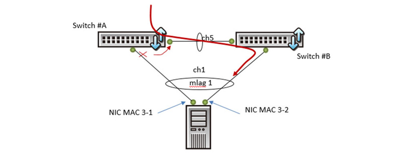
In this simple topology, LACP are created from switch A and switch B connections, and when MLAG is enabled. A 3rd party unit can perform LACP or the NIC teaming feature to connect with switch A and switch B accordingly. The MAC address of the 3rd party unit learned in switch A and switch B will synchronize with each other via the peer link. If one of the 3rd party unit’s connected ports is down in switch A or Switch B, the MAC addresses learned from the MLAG member ports will be synchronized to the MLAG peer link port of the switch. This design makes sure traffic can be re-directed to another switch via the peer link port for non-stop service. The below figure provides a more clearer view of the traffic re-direction for the MLAG feature.

MLAG enabled for traffic re-direction
MLAG to Support PXE Boot
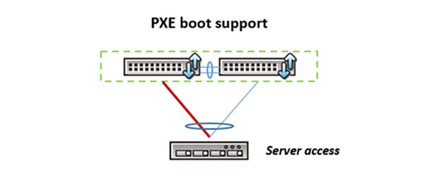
In the HA design topology, the server node can’t have the NIC teaming function perform if an Operation System (OS) has not been installed. Therefore, a server is used to perform a PXE boot to load the OS remotely. With two NIC cards installed in a server without an OS pre-load, a PXE boot can’t decide which path to go from to reach the ToR switch for OS installation. QNOS supports the LACP fallback feature for the PXE boot application. The below figure gives a picture of the LACP fallback feature, executing while the MLAG enabled devices are running. The path selection mechanism is decided by the LACP actor port priority. If it’s the same, the mechanism will be based on the port number connected to the switch. The path connected to a smaller port number will be chosen to support the PXE boot.

MLAG with LACP Fallback
MLAG Design with Rapid Spanning Tree Scenario
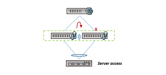
Although the MLAG enabled topology provides a loop free environment in the MLAG domain, some non-MLAG member ports can end up in a loop scenario. The QNOS MLAG design with Rapid Spanning Tree support prevents loop risk due to error configuration. In some of the application cases, it may still need to configure RSTP for non-MLAG member ports in the pair switches. The below figure shows one of the cases in the MLAG enabled environment with RSTP support for a loop free case.

Topology of MLAG with Rapid Spanning Tree
MLAG Design with IGMP Snooping and MLD Snooping
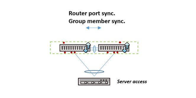
In the IGMP snooping enabled environment, a pair of switches which need to maintain a redundant design with the MLAG will need to synchronize the MACs learned from the multicast router port and group ports from each other in the paired switches. QNOS MLAG can support IGMP snooping for IPv4 and MLD snooping for IPv6 as shown in the figure below.

MLAG design to perform IGMP/MLD snooping
MLAG with ARP Table Synchronization
Using CLOS topology to scale out the networking design is common in today’s data center environment. The general term in CLOS topology used in a data center network is called a Spine to represent the aggregation switch and the Leaf switch could be a ToR (Top of Rack) switch or a middle layer switch between the Spine switch and ToR switch, for more scalable networking requirements. This network design can scale out the network scope in order for larger servers to be installed. In such a case, the common networking design for the Spine/Leaf architecture is to apply layer 3 protocols such as OSPF (Open Shortest Path First) and BGP (Border Gateway Protocol). The networking between Spine and Leaf usually has 4 to 8 paths which will require ECMP (Equal-cost multi-path) for traffic balance. While paired ToR switches perform MLAG, VRRP (Virtual Router Redundancy Protocol) is necessary to configure the assistance of the MLAG implementation in the layer 3 environment. Therefore, the active-active mode of VRRP is needed in the configuration. QNOS MLAG performs the ARP table synchronization in this case. The below figure shows the Layer 3 multi-path fabric topology with ToR redundancy design via MLAG and VRRP configuration.

Layer 3 multi-path fabric with ToR redundancy
Conclusion
MLAG is an important but complex feature. Depending on the application, it needs to work with VLAN, LACP, LACP fallback (PXE boot), RSTP, IGMP snooping, OFPF, BGP, ECMP and database synchronization. The MLAG supported in QNOS is a market-proven feature that meets HA data center networking designs.
For more information download the QCT MLAG WP at https://www.qct.io/Download/index/White-Paper

